Authors: Carla Coltharp, Kent Johnson, Wenliang Zhang, Chichung Wang, Kristin Roman, Felicia Ishola, David Cordover, Daniel Eversole, Clifford Hoyt, Peter Miller
Issue: 2019 American Association of Cancer Research Trade Show
Background
As the need for multiple biomarker assessment in immuneoncology has become more clear, multiplex fluorescent
immunohistochemistry (fIHC) techniques have become integral to
immune oncology research.
Multispectral approaches to fIHC improve quantitative
performance and signal specificity by ensuring removal of
autofluorescence signals and bleed-through between spectrallyadjacent dyes.
We have recently demonstrated a novel high-throughput scanning
approach (MOTiF™) that allows acquisition of a 7-color
multispectral slide scan in 5–10 minutes (1.5x1.5 cm).
Here, we demonstrate the spatial measurements that are made
possible by this high-throughput, translational workflow. These
measurements span the scales related to tumor biology from the
distance between nearest cell neighbors to the extent of the
invasive margin.
Methods
Phenoptics Workflow
Formalin-fixed paraffin-embedded (FFPE) samples of primary
tumors were stained using Opal™ reagents on a Leica BOND RX.
Sections from several primary tumor types were stained against 5
key markers in the field of immuno-oncology (CD8, FoxP3, PD-1,
PD-L1, CD68) along with a tumor marker (PanCK, PAX8, or
Sox10+S100 cocktail) and DAPI counterstain, resulting in 7 colors
on each slide.
Conventional and MOTiFTM multispectral scans (0.5 µm/pixel; 2.8 –
7.4 cm2) were acquired on Vectra Polaris® (9 – 26 min scan times).
Scans were viewed with a Phenochart™ version modified to divide
analysis regions into larger fields to reduce batch analysis times.
Cell segmentation and phenotyping were performed in inForm®.
Batch results from inForm® were merged and consolidated with the
phenoptrReports package1 in RStudio2 using R 3.5.23. Tumor
margin annotations were drawn and exported with QuPath4.
Heatmaps, histograms, and density plots were generated from
consolidated inForm® results with R scripts under development.
Multiplex Staining
Opal™ reagents allow multiplex fIHC staining of up to 8 antigens
with signal amplification and any combination of mouse and/or
rabbit primary antibodies.
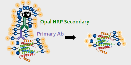
Fig 1. Opal™ Detection. The Opal HRP polymer amplifies IHC detection by covalently depositing multiple Opal fluorophores near the detected antigen. Then, antibodies are stripped to allow for sequential labeling of multiple markers.
Multispectral Imaging and Unmixing
With Vectra Polaris®, different combinations of agile LED bands, bandpass excitation filters, bandpass emission filters, and a liquid crystal tunable filter (LCTF) are used to select narrow spectral bands for imaging. Images from up to 40 narrow spectral bands are layered into a single multispectral image.

Fig 2. Unmixing in inForm® software.
(A) A multispectral image cube where each layer is taken at a different spectral range.
(B) Signals from all spectral layers are linearly unmixed using pure emission spectra for each fluorophore. Intensity values in the resulting unmixed image
(C) are directly related to the amount of each fluorophore present in each pixel.
7 Color Immuno-oncology Panel
FFPE tissue sections were stained with a 6-plex, 7-color Opal™ panel. The 6 markers in the panel combine to identify at least 12 different phenotypes of interest outlined below.
Phenotype Combinations with 7-color Panel
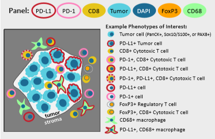
Unmixed 6-plex, 7-color Multispectral Digital Slide
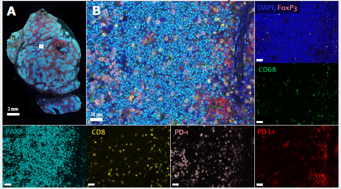
Fig 3. Multispectral scan of human lymphoma tissue stained with 7-color Opal™ panel: DAPI, PAX8 (Opal 690), CD8 (Opal Polaris 480), PD-1 (Opal Polaris 780), PD-L1 (Opal 520), CD68 (Opal 620), FoxP3 (Opal 570).
(A) Whole slide unmixed view from Phenochart™
(B) View of region outlined by white rectangle in A. Remaining panels show separate planes that comprise B (scale bar, 30 µm).
Unmixing Improves Sensitivity
Distinguishing two human melanoma tissues with different PD-L1 positivity. Both tissues were stained with DAPI, Sox10+S100 cocktail (Opal 690), CD8 (Opal Polaris 480), PD-1 (Opal Polaris 780), PD-L1 (Opal 520), CD68 (Opal 620), FoxP3 (Opal 570).
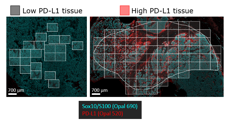
Fig 4A. Views of both tissues where only PD-L1 (red) and Sox10+S100 (cyan) are shown. Both images shown at the same image contrast for both stains.
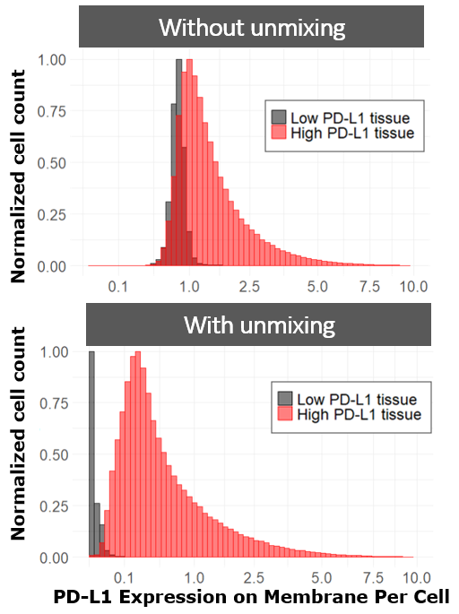
Fig 4B. Histograms of membrane PD-L1 (Opal 520) expression level for all cells detected in the white rectangular fields in A (square root mapping in X). (B, top) The distributions overlap without unmixing due to autofluorescence signal contribution in the Opal 520 channel (Opal 520 is spectrally similar to Alexa488 and FITC). (B, bottom) With unmixing, the distributions become easily distinguished.
Characterizing the Tumor and Tumor Microenvironment
Visualizing Heterogeneity Across Tissue Sections
Unmixed images were processed with inForm® software to phenotype each marker in the panel. Resulting phenotype data can be plotted as heatmaps of cell density (cells/mm2). These density maps reveal heterogeneity across the section that is not immediately apparent from viewing the original image.
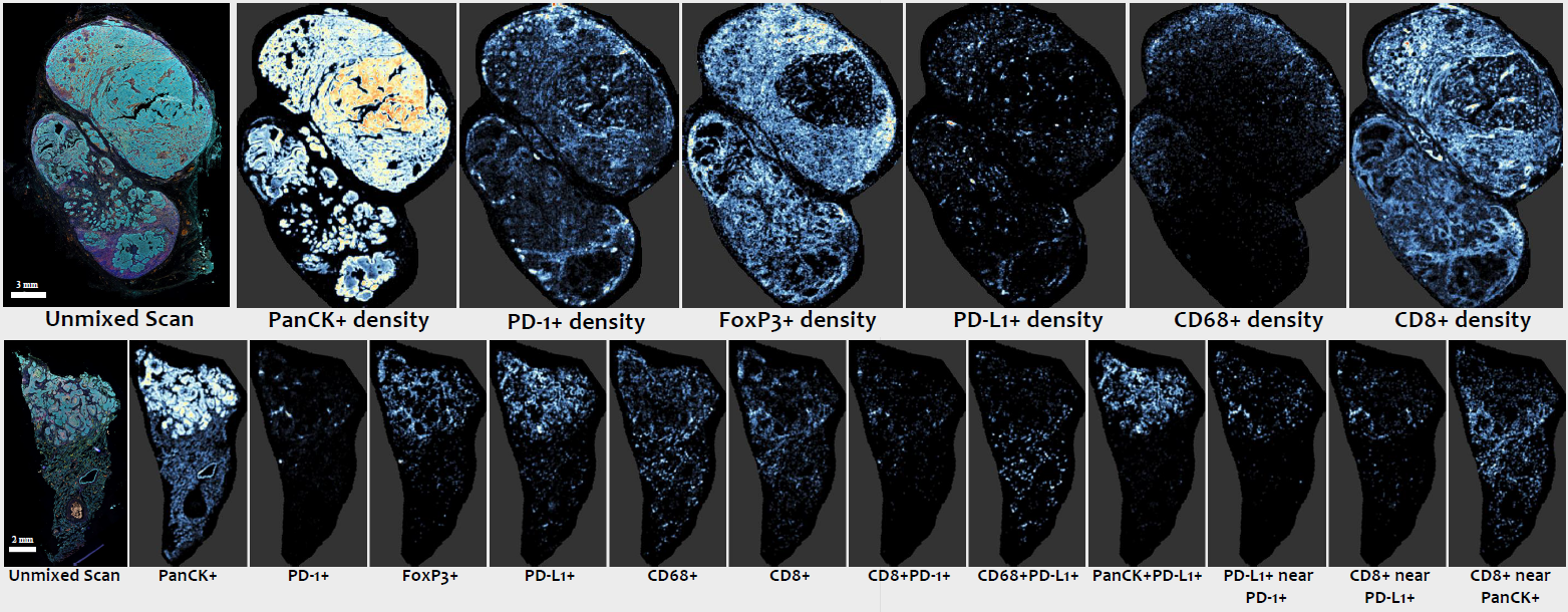 Fig 5. Cell density maps of a head and neck cancer tissue (top) and lung cancer tissue (bottom). 7-color Opal™ panel: DAPI, PanCK (Opal 690), CD8 (Opal Polaris 480), PD-1 (Opal Polaris 780), PD-L1 (Opal 520), CD68 (Opal 620), FoxP3 (Opal 570). Left-most panel is the unmixed multispectral scan. Remaining panels show heatmaps of cell density for different phenotypes (listed below each panel). Each panel has a different internal color scale. ‘Near’ indicates within 30 microns.
Mapping Organization within the Tumor Microenvironment

Fig 6. PD-L1 and lymphocyte organization around tumor in a human lung cancer.
(A) A second lung cancer tissue. Same panel and image format as Fig 5.
(B) Zoomed in view of relative cell density for each marker in the panel. Elliptical annotation overlaid to highlight that different markers reside at different radii outward from the tumor cells clusters.
(C) Hand-drawn tumor margin (thick white line) and blue bands spaced at 20 micron increments.
(D) Density of each marker within the bands shown in C. Peak densities for different markers are found at different distances outside the tumor margin, consistent with imagery in B.
Visualizing Heterogeneity Along a Tumor Margin
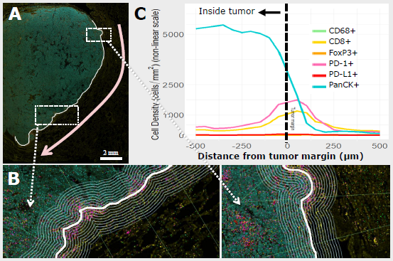
Fig 7. Cell density along an extended tumor margin.
(A) Hand drawn tumor margin (white) on a melanoma tissue. Same tissue and panel as Fig 4A, left.
(B) Zoomed in region of tumor margin showing bands spaced at 25 micron increments parallel to the margin and perpendicular straight lines that divide the margin into segments.
(C) Collapsed cell density plots across the entire tumor margin as in Fig. 6D where left is inside tumor
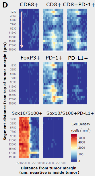
Fig 7D. Heatmaps of cell density showing hot spots of immune activity along the tumor margin. The X axis in D is the same as in C. The Y axis in D represents segments along the tumor margin in the direction shown by the pink arrow in A. All heatmaps share the same color scale (bottom, right).
Conclusions
Spatial analyses of MOTiF™ multispectral scans
showed wide variety among the tumor sections and
within individual tumor sections. We observed
differences in the overall density of individual markers,
and further distinctions when looking at the local
proximities of marker combinations that could not be
observed with a conventional 3- or 4-color slide scan.
Furthermore, when compared with results from
analogous scans analyzed without spectral unmixing,
the MOTiF™ imagery showed a marked improvement
in the dynamic range of detected positive cells.
These tools for spatial analyses of MOTiF™ highthroughput 7-color multispectral slide scans provide
translational researchers the ability to probe a whole
slide section with the necessary breadth and depth to
describe the complex heterogeneity of the tumor
microenvironment.
